Pin mapping
| APU3/4 | TPM1a |
|---|---|
| 1 (LFRAME) | 11 |
| 2 (LAD3) | 9 |
| 3 (LAD2) | 7 |
| 4 (LAD1) | 5 |
| 5 (LAD0) | 3 |
| 6 (GND) | 2, 4, 6, 8, 10, 12, 17 |
| 7 (LPCRST) | 13 |
| 8 (LPCCLK1) | 1 |
| 9 (V3) | 18 |
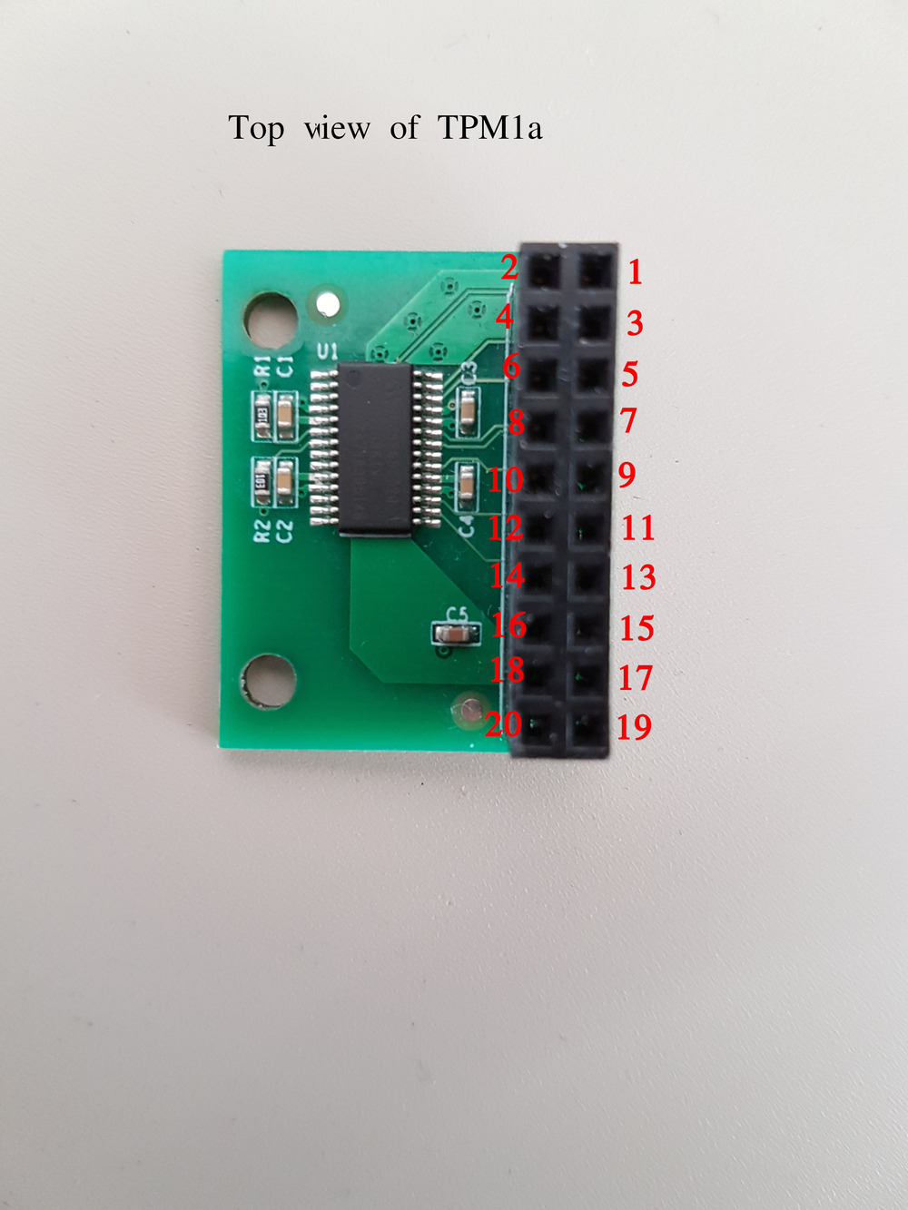
TPM1a
- At least one pin of no. 2, 4, 6, 8, 10, 12 and 17 should be connected to GND and pin no. 18 should be connected to V3.
- Pins no. 14, 15, 16, 19 and 20 stay unconnected.
APU3/4
- Pin no. 6 should be connected to GND and pin no. 9 should be connected to V3.
Important!
It should be noticed, that the LPC debug holes on apu board are much smaller, so regular pin header will not fit there.